Nulo

Why a Class A die

Why a Class A Die is a Class A Die?

Most of the companies which develop tools or dies claim about manufacturing class-A dies. 

But are they genuinely class A dies? There are three categories of dies – A, B & C and there can be two types of class A dies. The differences between them depend on the tooling quality and materials used in manufacturing.

Here, we would try to summarize such differences and understand why a Class A die is a class A die. Let’s dive in.

Class A - Type 1

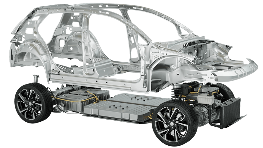
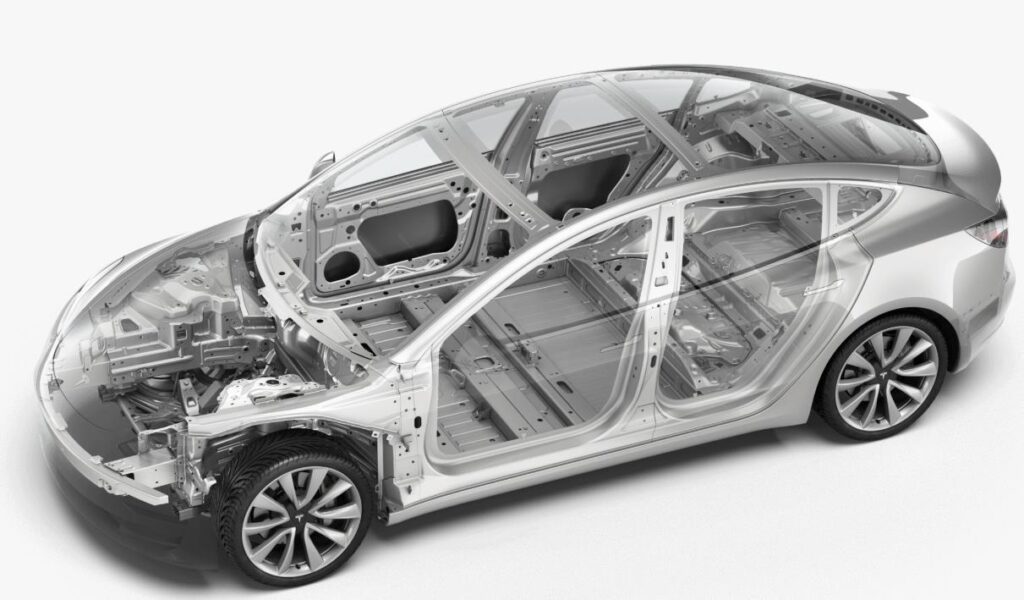
Class A (Type 1) is usually a larger drawing and stretching die used to manufacture parts, which need a smooth, defect free, and aesthetically superior surface. Exterior BIW Parts / Skin Panels such as Body Side Outer, Tail Gate, Fender, Roof, Hood and Outer Doors are few examples of parts which are made with this type of tooling. 

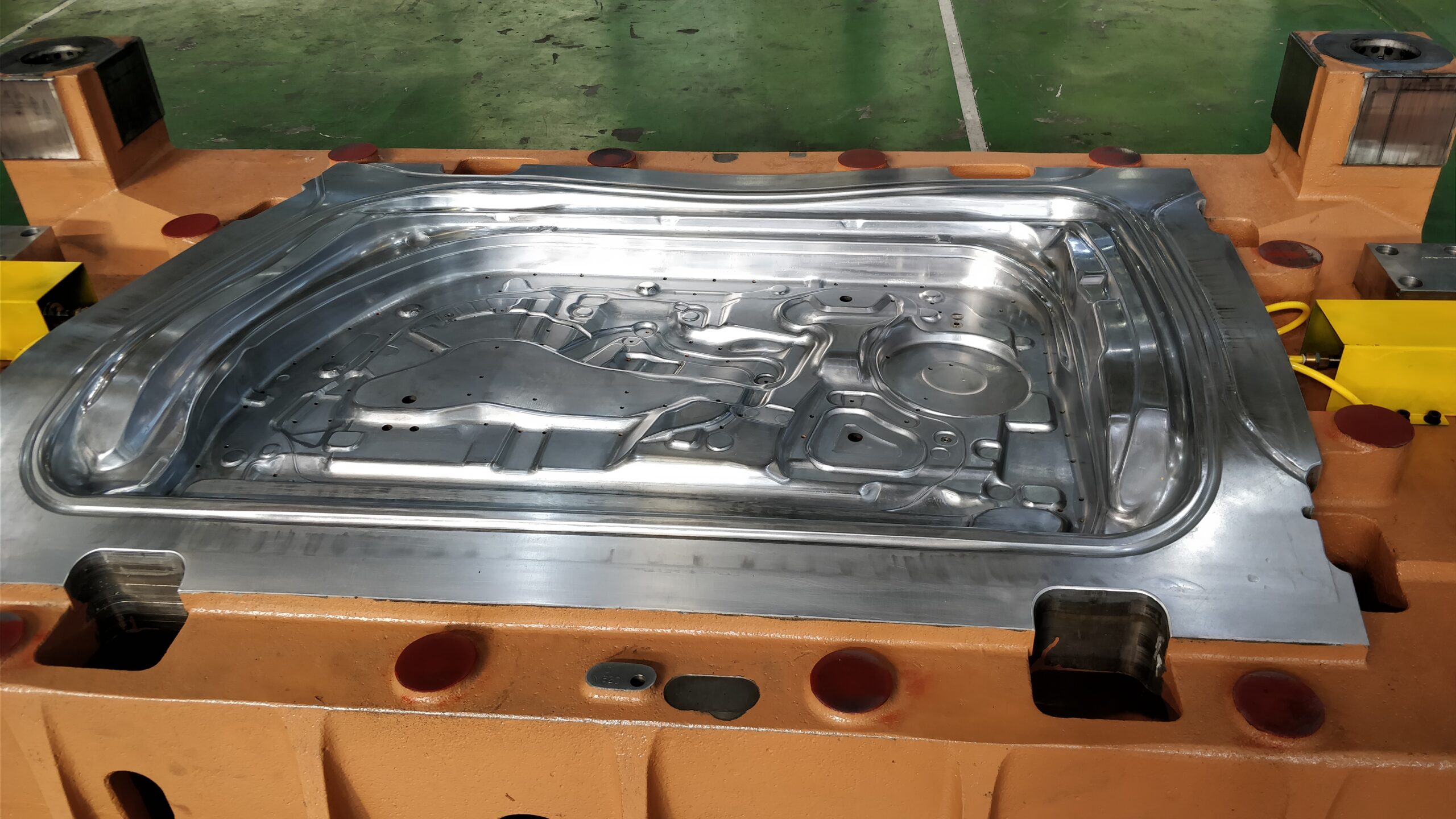
The forming dies must have the surface finishes same as or better than the real part surface requirements. As most exterior Body / BIW panels are shaped or contoured, the grinding and finishing process needs a lot of manual work. Thus, the toolmaker should be highly skilled and experienced at tool grinding and finishing. The toolmaker should produce a spot-free (high or low spots) surface using polishing papers, stones, and hand-held grinders as even the smallest defects in the die surface will be visible on the stamped panel.

Class A dies also should be run in a clean environment. Even the smallest pieces of lint from

the press operator’s gloves getting into the die will leave a visible surface defect in the stamped part.

Parts stamped with class A dies are usually coated with a highlight oil to look like a shiny clear coat and then move to a “highlight room,” a room or awning with bright lights, for careful examination from all angles and perspectives to check for the visible skin defect on the stamped panel.

Class A - Type 2

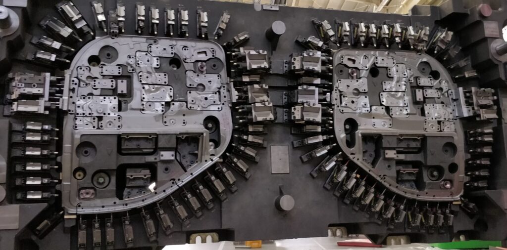
Class A (Type 2) is designed & manufactured with the highest precision and made of the top-quality materials, regardless of the price. These dies can produce very high volumes of parts and be under process for years, like high-speed (500 SPM or greater) progressive dies. Such types of ultraprecision die usually have aluminium die shoes and solid carbide / ceramic functional parts. When tool steel is used, it is of the highest Crucible Particle Metallurgy grade.

Some of these types of progressive dies are running at 1500 SPM and can produce multiple parts per stroke. This shows that the finest material and ultimate level of accuracy is required to manufacture these dies / tools.

Class B

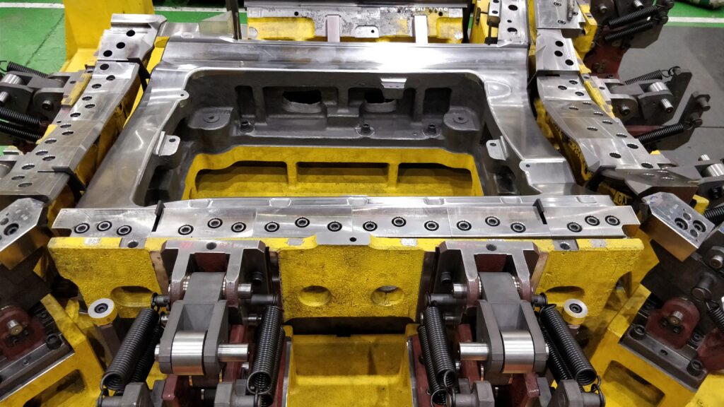
Most dies used for manufacturing belong to the class B category and are made of typical tool steels such as A2, D2, SKD11 and SLD Magic. Some of them are made of materials, like solid carbide. Such tools are designed, developed and manufactures with materials that tend to stay for the expected production volume required. These type of tools are often used in the automotive industry, as the tooling requires producing parts for a specific car model as long as it’s under production. Class B tools are good enough to perform the task for as long as required.

Class C

Class C tools are designed, developed, and manufactured with low-cost materials and methods to produce satisfactory parts. They are usually temporary, low volume or prototype tools used to manufacture a few hundred parts. Such tools may be made of affordable tool steel, low-carbon steel, or Kirtsite, which contains zinc and alloying parts of copper, aluminium, and magnesium. As Kirtsite is machinable and recyclable, it’s perfect for low-volume work, such as producing large interior and exterior prototype body / BIW panels.

A toolmaker is the right person for making the decision to classify any tool. However, Stampers must clearly chalk out and explain the requirements to the toolmakers related to the Press Specifications, Volume, Die Life, Accuracy, Aesthetics / Surface Quality requirements and Die Construction Standard. These specifications, information and standards must be followed by the toolmaker to produce the desired tool quality. 

Choosing the right Class of Die for a given application is a key to success in a long run!

Inside the Electric Heart

EV Battery

Electric vehicle (EV) battery manufacturing involves the production of batteries specifically designed for use in electric vehicles. The process includes the production of battery cells, assembly of cells into battery packs, and integration of battery packs into vehicles. Key factors in EV battery manufacturing include the selection of battery chemistries, production processes, and the supply chain for raw materials. Some of the major players in the EV battery manufacturing industry include Tesla, Panasonic, LG Chem, and CATL.

Key Components of EV Battery

The key components of an Electric Vehicle Battery include:

Battery Cells: These are the individual units that store electrical energy and are connected together to form a battery pack. Each cell typically contains a positive and negative electrode, separated by a porous membrane, and an electrolyte solution.

Battery Management System (BMS): This is an electronic control unit that manages the operation of the battery pack, including monitoring the voltage, temperature, and state of charge of each cell, as well as balancing the charge and discharge of the cells to ensure optimal performance and longevity.

Cooling System or Thermal Management System (TMS): This is a system that helps regulate the temperature of the battery pack to prevent overheating and degradation of the cells. It typically includes cooling channels or a liquid cooling system.

Structural Casing: This is a rigid, protective casing that holds the battery cells together and provides physical support and protection for the battery pack. It is typically made from materials such as aluminum or composite materials.

Electrical Connectors: These are the components that connect the battery pack to the car’s electrical system, including the electric motor, charging port, and other components.

Together, these components work to store and deliver electrical energy to power the electric motor and other systems in the car. The specific design and materials used in an electric car battery can vary depending on factors such as the vehicle type, performance requirements, and cost considerations.

Structural Casing / Battery Casing

The structural casing of an electric car battery pack is an essential component that provides mechanical support and protection to the battery cells and other components. The casing is typically made from lightweight materials that offer high strength and durability, such as aluminum or composite materials.

The design of the casing can vary depending on the specific vehicle model and battery pack configuration, but it typically includes the following components:

1. Main frame: This is the main structure of the casing, which holds the battery cells in place and distributes the loads and stresses across the structure.

2. Side Panels: These are the panels that cover the sides of the battery pack, providing additional protection and support to the cells.

3. Top and Bottom Covers: These are the covers that seal the top and bottom of the battery pack, protecting the cells from external elements and providing a flat mounting surface for the battery.

4. Cooling Channels: These are channels or ducts that allow air or coolant to flow through the battery pack to regulate the temperature of the cells and prevent overheating.

5. Mounting Points: These are the points on the casing where the battery pack is mounted to the vehicle chassis, typically using bolts or other fasteners.

6. Access Points: These are openings or panels in the casing that allow access to the battery cells or other components for maintenance or repair.

The structural casing of an electric car battery pack is designed to withstand various types of loads and stresses, including vibration, impact, and thermal expansion. The casing is typically designed and tested to meet various safety standards and regulations, such as crash safety, fire safety, and environmental requirements.

Material for Structural Parts

Various materials can be used for the structural parts of an Electric Car, including:

Aluminum: Aluminum is a lightweight, corrosion-resistant material that is commonly used for the structural parts of electric cars, including the battery casing, body frame, and suspension components. It offers high strength-to-weight ratio and good stiffness, making it an excellent choice for reducing the overall weight of the vehicle.

Carbon Fiber Composites: Carbon fiber composites are lightweight, high-strength materials that offer superior stiffness and durability compared to aluminum. They are often used for the body panels and other structural parts of high-end electric cars to improve performance and reduce weight.

Steel: Steel is a strong, durable material that is commonly used for the structural parts of electric cars, including the body frame, chassis, and suspension components. It offers good crash resistance and is often used in combination with other materials to achieve a balance of strength, stiffness, and weight.

Magnesium: Magnesium is a lightweight, high-strength material that is often used for the structural parts of electric cars, including the body frame, suspension components, and steering system. It offers good corrosion resistance and is often used in combination with other materials to reduce weight.

Plastics: Plastics are lightweight, corrosion-resistant materials that are commonly used for the body panels and other non-structural parts of electric cars. They offer good design flexibility and can be easily molded into complex shapes.

The choice of material for various structural parts of an electric car depends on several factors, including the performance requirements, cost considerations, and design specifications. A combination of different materials may be used to achieve the desired balance of strength, stiffness, weight, and durability.

Aluminium Extrusion in EV Battery

Aluminum extrusion is a common manufacturing process used to produce various components of the structural casing for an electric car battery pack. Extrusion involves forcing a heated aluminum billet through a die with a specific cross-sectional profile to create a long, continuous length of the desired shape. This process is used to create complex shapes with consistent cross-sections and tight tolerances.

The advantages of using aluminum extrusion for the structural casing of an electric car battery pack include:

1. Lightweight: Aluminum is a lightweight material, and using extrusion allows for the creation of complex shapes with thinner walls, reducing the weight of the final product.

2. High Strength: Aluminum extrusions have high strength-to-weight ratios and can be designed to meet the specific strength requirements of the structural casing.

3. Design Flexibility: Extrusion allows for the creation of complex shapes and profiles with consistent cross-sections, enabling the design of the structural casing to be tailored to the specific requirements of the battery pack.

4. Corrosion Resistance: Aluminum is a naturally corrosion-resistant material, which reduces the need for protective coatings or treatments.

5. Cost-effective: Extrusion is a cost-effective manufacturing process, allowing for the creation of high-quality components at a lower cost compared to other manufacturing methods.

Overall, the use of aluminum extrusion in the manufacturing of the structural casing for an electric car battery pack offers several benefits, including weight reduction, strength, design flexibility, corrosion resistance, and cost-effectiveness.

Aluminum extrusion can be used to manufacture several components of the structural casing for an electric car battery pack. Some examples of parts that can be made by extrusion include:

Frame: The main frame of the structural casing can be extruded as a long, continuous length with a specific cross-sectional profile. The profile can be designed to provide the required strength and stiffness to support the weight of the battery pack.

Side Panels: The side panels of the structural casing can also be extruded as long, continuous lengths with specific cross-sectional profiles. These panels can be designed to provide the required strength and stiffness while also incorporating features such as mounting points for the battery cells and cooling system components.

Covers: The covers of the structural casing, which protect the battery cells and provide access for maintenance and repairs, can also be extruded. These covers can be designed with specific features such as channels for wiring and connectors.

Brackets and Mounting Points: Extrusion can also be used to create brackets and mounting points for the various components of the battery pack, such as the cooling system and electrical connectors. These brackets and mounting points can be designed to provide the required strength and stiffness while also reducing the weight of the overall assembly.

Overall, the use of aluminum extrusion in the manufacturing of the structural casing for an electric car battery pack provides several benefits, including the ability to create complex shapes and profiles, design flexibility, and cost-effectiveness.

Stamping is another manufacturing process that can be used to create various components of the structural casing for an electric car battery pack. 

Hot Stamping

Hot Stamping Process

As it is heated in a 900+ degree-C furnace, hot stamp blank material becomes very sticky, resulting in friction coefficients of 40 percent or more. Material coatings used to prevent decarburization and scale formation during blank heating can be very abrasive to tool surfaces. No lubricants can be used because of the ultrahigh temperatures. As a result, managing friction is critical to avoid excessive thinning, splitting, and cracking in the part, as well as excessive die wear from the abrasion

Mitigating Friction

Several methods are used to control friction. The part may be crash-formed without pressure pads when part geometry allows the free flow of material into the die cavity during forming. This is possible if there is not too much surface contact between the blank and die.

However, other methods are needed to control the part during forming to prevent its unintended lateral shifting, which would create the need for extra material addenda and post-forming trimming. Edge or pin gauges commonly are used to locate the blank during die loading. Stick pads may be used to grip or form the material in the center of the part. This is the opposite of most large cold stamping operations during which draw beads control material movement and ensure sufficient material stretch to remove loose metal and achieve a consistent form.

Because no lubrication is used and the material is very sticky, the primary forming challenges are friction-induced wrinkling of the material and keeping it hot enough to avoid hardening before the part is fully formed.

As soon as the heated material contacts the much colder die (typically below 200 degrees C), the heat starts transferring to the die, starting the rapid quench process. Consequently, forming should be done very quickly (usually in less than one second after the blank contacts the die) to ensure that the part remains pliable until it is fully formed. Minimizing the surface contact of the material being formed until the last part of the stroke will improve the process generally, and friction-caused thinning will be reduced.

While crash forming often will be the best die process, compression of flanges on the inside radii can cause wrinkling, with unacceptable distortion, or double metal after forming. In this case, a wrinkle control gapped pad is used to prevent excessive wrinkle height from forming. Nitrogen cylinders hold the pad apart to allow free metal flow into the cavity. These gap cylinders are compressed at the bottom of stroke to iron out the wrinkles before quenching.

To further complicate the situation, the blank expands when it is heated and the part shrinks after it cools off during quench. This makes it more difficult to gauge and control the part during forming, since gauging has to accommodate the shrinkage without losing effectiveness and allowing the part to move. That would be counterproductive to any attempts to use developed trim lines to reduce the cost of secondary laser cutting operations for trimming edges and cutting holes.

One of the more recent developments is hot piercing in form dies. After the part is fully formed at the bottom of stroke, holes are pierced before the part hardens. These holes can be used for finished part holes or they can be used as sacrificial manufacturing holes, often for locating the formed part in secondary laser cutting operations.

Hot trimming is also possible, and if it can eliminate laser trimming, it may be a viable strategy. However, both hot piercing and hot trimming are complex and are considered high-maintenance.

Effects on Die during Quenching

The quenching process rapidly cools the material. The temperature must drop at a rate in excess of 27 kelvins per second to change the austenitic microstructure into martensitic, without going through any ferritic or bainitic phases, which would prevent martensite formation. This requires sufficiently cool die surfaces (below 200 degrees C) that can absorb the heat from the part and transfer it to the water cooling channels that remove the heat from the die.

The die surface heat transfer coefficient depends on contact pressure and surface roughness. It is important to achieve uniform contact pressure, even on side walls, and to keep the tool smooth and clean. It is also important to have sufficient press tonnage. When debris, such as a material coating, accumulates, the die must be cleaned or the contact pressure will drop quickly. That will slow down the quench process to the point where quench rates are too slow, resulting in soft spots caused by bainite formations.

The same contact pressure deterioration can result from tool surface abrasion (typically male radii) that causes slower quenching. This increases cycle time and part cost. It also can cause part distortion by quenching unevenly, leaving residual stresses from uneven part shrinkage. That can contribute to inconsistent geometry after laser cutting or assembly. Quench rates also depend on proper distance of cooling channels from the surface and on thermal conductivity of the tool steel at elevated temperatures.

Last, the heat transfers into the water and is carried out of the tool. Water cooling typically occurs through drilled holes in the die. It is important to make sure that the water channels are matched to the facility’s water chiller capabilities (temperature, pressure, flow) so the tool uses all of the available chiller capacity to quench as quickly as possible.

It is also important to balance water flows between parallel cooling channels to maintain uniform quenching of the part, especially if the part geometry is sensitive to quench uniformity. Also, water flows must be turbulent to improve heat transfer capacity. High water pressure creates better cooling channel heat transfer coefficients and, therefore, more efficient heat transfer.

Thermographic cameras and infrared pyrometers are typical measuring instruments used to assess quench uniformity and quench rate, as well as part and die hot spots for process control. Changes in thermographic or pyrometric readings indicate problems that need to be resolved, such as clogged water lines, debris in the die, and worn tooling.

Temperature measurement instruments are also used to develop the thermal process windows for the part production. The windows are used for process control and documentation to determine how many seconds to quench, press tonnage, part leaving temperatures, and so forth.

Hot Form & Quench Die Maintenance

Contrary to popular belief, Lorem Ipsum is not simply random text. It has roots in a piece of classical Latin literature from 45 BC, making it over 2000 years old. Richard McClintock, a Latin professor at Hampden-Sydney College in Virginia, looked up one of the more obscure Latin words, consectetur, from a Lorem Ipsum passage, and going through the cites of the word in classical literature, discovered the undoubtable source. Lorem Ipsum comes from sections 1.10.32 and 1.10.33 of “de Finibus Bonorum et Malorum” (The Extremes of Good and Evil) by Cicero, written in 45 BC.Hot form and quench dies require more maintenance than conventional cold stamping dies because of the thermal expansion and contraction that takes place each press cycle. As the die heats up during quench, and then cools off during part unload, blank load, and part forming, heat checking occurs, which can cause tool cracks and water leaks. As a result, tool steels are generally H13 or better grade materials that can take the thermal shock as well as forming shock loads and abrasive materials.

Typically, water channels are cross-drilled into blocks that are assembled with O-ring seals. These tend to degrade over time and are replaced whenever tools are disassembled for maintenance and cleaning. Also, O-rings are exposed to heat damage between the surface and the water channel. Proper compression of O-rings is important to eliminate water leaks in the tools.

Tool steel cracks caused by thermal expansion, contraction, and heat checking usually occur between the surface and water channels. When excessive cracks are seen, a higher-quality H13 ESR variant tool steel may be warranted. Cracks can sometimes be repaired by welding.

When excessive die wear occurs, it may become necessary to replace the forming steels or to recut die surfaces. Water cooling channels make recutting more difficult, as it is important to maintain proper spacing from the die surface to maintain die strength and cracking resistance. Recuts generally are quite limited with hot form and quench tools, and they are difficult to achieve with deep-draw section side walls.

Hot form and quench die tool steels must be replaced when they become too difficult to maintain. Replacement is complicated by the need for the new forming block to match mating sections of adjacent blocks. The adjacent die surfaces may no longer match original CAD models or scans of original dies, and the replacement detail has to be adjusted to match the adjacent, slightly worn blocks.

Significant damage will occur to the form and quench tool if it is double-hit by loading a blank onto a previously formed part that was dropped in the die while it was being unloaded. Side wall angles are often steep, and these become very effective wedges that tend to bend or break die steel sections. Although the die might survive, it may lose contact pressure on the side walls and consequently not properly quench without extra quench time and product cost. Automation units should be carefully tracking part flow to ensure that dies are unloaded properly and not double-hit. Redundant double-blank detection is highly warranted.

Product Revisions Affecting Die Build

As with all stamping tools, product revisions may require the adjustment, or even replacement, of the tooling. With hot stamp form and quench dies, this can become more complicated since the tools are more difficult to machine and weld because of the through-hardened tool steel blocks and because they contain cooling channels.

When starting to build a hot stamp tool, it is important to assess the potential of product revisions and their nature. It may be possible to protect a tool to a limited degree (if there is uncertainty about the product design) by allowing extra material in localized areas of the die, and then removing the excess before going into production. Part of this assessment also should include deciding whether the part design can be made as currently designed, or if it will require some changes to radii or other features.

Formability simulations are important tools to use in the assessments. These can reduce risk so that a production tool can be made without having to build in provisions for minor changes. If simulations show risks, product changes can be made before the tooling is started. However, if there are questions about formability, or uncertainty about product design-driven potential revisions, it may make sense to produce low-cost physical prototype tools to prove out formability and assess product functionality in early vehicle builds.

Three levels of prototype tooling are available, typically. These are geometry only; geometry plus heat treating; and production-intent prototype for evaluation of developed trims and wrinkle/thinning control. Prototype tooling can be easily remachined or changed before launching the production tooling.

The 65th Square

In the fast-paced world of business, it’s essential to have a strategy that allows you to maximize your resources and achieve your goals. That’s where the 65th Square strategy comes in – a powerful approach that leverages the art of resource utilization to help you achieve more, with less.

The 65th Square concept is based on the idea of a chessboard, with 64 squares representing all the resources at your disposal. However, there is one square that holds the key to unlocking your full potential – the 65th square. This square represents the art of utilizing your resources in the most effective way possible, and by adopting this strategy, you’ll be able to maximize the impact of every resource you have at your disposal.

One of the key benefits of the 65th Square strategy is that it helps to eliminate waste and inefficiency. By focusing on effective resource utilization, you can streamline your processes, cut down on unnecessary costs, and optimize your results. This, in turn, will allow you to allocate more resources towards areas that are truly important to your business.

In addition to reducing waste, the 65th Square strategy can also help you identify new opportunities. By taking a strategic approach to resource utilization, you’ll be able to see opportunities that you might have missed before. This could include new markets, new products, or even new partnerships.

To implement the 65th Square strategy in your business, start by taking a close look at your current resource utilization. Identify areas where you could be more efficient, and look for ways to optimize your processes. Then, focus on leveraging your resources to achieve your strategic goals, whether that’s increasing your market share, expanding your reach, or developing new products.

In conclusion, the 65th Square strategy offers a powerful approach to resource utilization that can help you achieve more, with less. By focusing on effective resource utilization, you’ll be able to eliminate waste, identify new opportunities, and maximize your results. So why settle for 64 squares, when you can claim the 65th square and unlock your full business potential? Start your journey today!

Insights on The 65th Square Strategy

1. Focus on Priorities: The 65th Square strategy encourages you to focus on your priorities, and allocate your resources accordingly. By focusing on what’s truly important, you’ll be able to get the most out of your resources and achieve your goals more effectively.

2. Collaboration: Effective resource utilization often requires collaboration, and the 65th Square strategy encourages you to work with others to achieve your goals. Whether that’s partnering with other businesses, working with suppliers, or leveraging your employees’ skills, collaboration can help you optimize your results.

3. Continuous Improvement: The 65th Square strategy is not a one-time solution, but a continuous journey of improvement. By continually re-evaluating your resource utilization, you can identify new opportunities for optimization and keep your business on the path to success.

4. Measurement and Tracking: To effectively implement the 65th Square strategy, it’s important to measure and track your results. This will help you identify areas for improvement, and measure the impact of your efforts over time.

5. Culture Change: Adopting the 65th Square strategy often requires a shift in culture and mindset, particularly for organizations that are used to traditional resource utilization methods. Encouraging a culture of continuous improvement and effective resource utilization is key to the success of the 65th Square strategy.

6. Communication: Effective communication is crucial to the success of the 65th Square strategy. By clearly communicating your goals, expectations, and processes, you’ll be able to ensure that everyone is working towards a common goal.

By keeping these insights in mind, you’ll be able to effectively implement the 65th Square strategy in your business and unlock your full potential. Remember, the 65th Square represents the art of resource utilization, and by embracing this approach, you’ll be able to achieve more, with less.

How to Implement The 65th Square Strategy - Case Study

Company: ABC Inc.

Industry: Manufacturing

ABC Inc. is a mid-sized manufacturing company that specializes in producing high-quality products. Despite their success, the company was facing challenges in terms of efficiency and resource utilization. The management team recognized the need for a new approach and decided to adopt the 65th Square strategy.

Step 1: Assessment

The first step was to assess the current resource utilization. The management team conducted a thorough analysis of their processes and identified several areas where they could be more efficient. This included streamlining production processes, reducing waste, and improving the utilization of their employees’ time and skills.

Step 2: Prioritization

Once the areas for improvement were identified, the management team prioritized their efforts. They focused on the areas that would have the biggest impact on the company’s bottom line, including reducing waste and improving efficiency.

Step 3: Collaboration

To achieve their goals, the management team realized that they needed to collaborate with their employees. They encouraged their employees to provide feedback and suggestions, and worked together to implement new processes and systems that would improve efficiency.

Step 4: Implementation

The management team worked tirelessly to implement their 65th Square strategy. They introduced new systems to streamline production processes, reduce waste, and improve employee utilization. They also implemented a new culture of continuous improvement, encouraging their employees to look for ways to optimize their processes.

Step 5: Measurement and Tracking

Finally, the management team monitored their progress and tracked their results. They found that their 65th Square strategy was having a significant impact on their bottom line. They reduced waste, improved efficiency, and increased their competitiveness in the market.

This example shows how the 65th Square strategy can be effectively implemented in a manufacturing company. By focusing on resource utilization, ABC Inc. was able to achieve significant improvements in their processes, culture, and bottom line. The 65th Square strategy is a powerful tool that can help companies of all sizes and industries to achieve more, with less.

BIW for Electric Vehicle

BIW for Electric Vehicle - Differentiator & Skills Required

Body-in-White (BIW) refers to the initial stage of the automobile body assembly process where individual sheet metal components are welded together to form the car’s structure.

In the case of electric vehicles (EVs), the BIW process presents several unique challenges and opportunities.

One major difference is the weight of the vehicle, as EVs typically have a heavier battery pack and fewer internal combustion components, which affects the design and construction of the BIW. This requires a different approach to structural design, welding, and corrosion protection.

Another factor is the lack of a traditional engine, which frees up space in the vehicle that can be used for other components or for more passenger room. Additionally, the high-voltage battery pack and electric drivetrain require specialized safety measures in the BIW to protect against electrical hazards.

EVs also offer the opportunity to use lightweight materials such as aluminum or composites, which can improve the vehicle’s energy efficiency and reduce weight.

In conclusion, the BIW process for EVs requires a new approach to design and construction to accommodate the unique requirements of electric vehicles, but it also presents the opportunity to use new materials and techniques to improve the efficiency and performance of these vehicles.

ICE Vehicle BIW v/s Electric Vehicle BIW

The Body-in-White (BIW) of an internal combustion engine (ICE) vehicle and an electric vehicle (EV) have some important differences that reflect the different requirements and design constraints of these two types of vehicles. Some of these differences are:

1. Material selection: The BIW of an EV is often made of lightweight materials such as aluminum and high-strength steels to reduce the overall weight of the vehicle and increase energy efficiency. In contrast, the BIW of an ICE vehicle is often made of more conventional materials such as low strength steel and iron.

2. Component design: The design of BIW components for EVs is often influenced by the need to accommodate the electric drivetrain, batteries, and other components, which can result in more complex shapes and tight packaging requirements. The design of BIW components for ICE vehicles is less constrained by these requirements and can be simpler.

3. Manufacturing processes: The manufacturing processes used to produce the BIW components for EVs may differ from those used for ICE vehicles due to the different materials and design requirements. For example, the use of lightweight materials in EVs may require the use of different forming and joining methods, such as laser welding and friction stir welding.

4. Crash safety: The design of the BIW for EVs must take into account the need to provide adequate crash protection for the electric drivetrain and batteries, which can add complexity to the design and require additional materials and reinforcement.

5. Corrosion protection: The design of the BIW for EVs must take into account the potential for corrosion due to the presence of high-voltage electrical components and the use of lightweight materials, which may require the use of specialized coatings and treatments.

In conclusion, the differentiation between the BIW of an ICE vehicle and an EV reflects the different requirements and design constraints of these two types of vehicles, and requires careful consideration of materials, component design, manufacturing processes, crash safety, and corrosion protection.

Skills for a BIW Development for Electric Vehicle

Developing a Body-in-White (BIW) for an electric vehicle (EV) requires a combination of technical skills and knowledge in several areas, including:

1. Structural design: A thorough understanding of vehicle dynamics, crash safety, and materials science is required to design a BIW that meets regulatory requirements and provides a safe and robust structure for the vehicle.

2. Manufacturing engineering: Experience with advanced manufacturing techniques such as laser welding, resistance spot welding, and hot stamping is essential for producing high-quality BIW components with consistent tolerances.

3. Materials science: Knowledge of lightweight materials such as aluminum, magnesium, composites, and high-strength steels is required to choose the best materials for the BIW, given the specific requirements of the EV.

4. Electrical safety: Knowledge of high-voltage electrical systems and safety standards is necessary to design a BIW that protects against electrical hazards and meets regulatory requirements.

5. Tool and die design: Experience with tool and die design is necessary to produce complex BIW components with tight tolerances and consistent quality.

6. Computer-aided design (CAD) and simulation: Proficiency in using CAD and simulation software is critical for designing, analyzing, and optimizing the BIW components and the overall vehicle structure.

In conclusion, developing a BIW for an EV requires a cross-functional team with expertise in several technical areas, including structural design, manufacturing engineering, materials science, electrical safety, tool and die design, and computer-aided design and simulation.

CAD Design & CAE Analysis

Key Points in the Development of a BIW for Electric Vehicle

The development of press dies for the Body-in-White (BIW) of an electric vehicle (EV) requires a careful consideration of several key points, including:

1. Tolerance and quality: Press dies must be designed to produce components with tight tolerances and consistent quality, as deviations from the desired shape can impact the overall performance and safety of the vehicle.

2. Lightweight materials: The use of lightweight materials such as aluminum and high-strength steels in the BIW of EVs requires the press dies to be designed to form these materials without causing damage or impairing their strength properties.

3. Complex shapes: The design of press dies for EVs must take into account the need to form complex shapes that meet the specific requirements of the BIW, including crash safety, aerodynamics, and packaging.

4. Durability and wear resistance: Press dies are subjected to high levels of stress and strain during the stamping process, so they must be designed and made of materials that provide good durability and wear resistance to ensure long-lasting performance.

5. Simulation and testing: Computer-aided design (CAD) and simulation software can be used to design and optimize the press dies, while physical testing can validate their performance and ensure they meet the required standards.

6. Cost-effectiveness: The press dies must be designed and produced in a cost-effective manner to minimize the overall cost of the BIW production process and maximize the competitiveness of the EV.

In conclusion, the development of press dies for the BIW of EVs requires a careful balance of technical considerations, such as tolerance and quality, materials, and shape, and practical considerations, such as durability, cost, and efficiency, to ensure that the press dies meet the performance and cost requirements of the EV industry.

How NULO can Support?

NULO can support the entire Body-in-White (BIW) development for an electric vehicle (EV) by providing a range of specialized services and expertise, including:

Design and engineering services: NULO can offer design and engineering services to help develop the BIW components and overall vehicle structure, taking into account the specific requirements of the EV, such as crash safety, aerodynamics, and packaging.

Prototype and testing services: NULO can provide prototype development and testing services to validate the design and performance of the BIW components and overall vehicle structure, including crash testing, fatigue testing, and corrosion testing.

Manufacturing support: NULO can provide support for the manufacturing of the BIW components, including the selection of materials and processes, the design of tooling and fixtures, and the optimization of the production line.

Quality control and certification: NULO can provide quality control and certification services to ensure that the BIW components and overall vehicle structure meet the required standards for safety, performance, and reliability.

Regulatory compliance: NULO can provide support to ensure that the BIW meets the regulatory requirements and safety standards for EVs, including crash safety, electrical safety, and environmental regulations.

NULO can play a critical role in supporting the entire BIW development process for EVs, providing a range of specialized services and expertise in design and engineering, prototyping and testing, manufacturing, quality control, and regulatory compliance.

Virtual Officers

Don't let location and time zones hold you back - with virtual officers, your business has access to top talent from anywhere in the world."

Virtual officers can bring value addition and cost efficiency to businesses by providing their services remotely to multiple companies. This allows businesses to access a wider pool of talent while reducing costs associated with traditional in-person support. Virtual officers can work on flexible schedules, making it possible for businesses to access support when they need it most. Additionally, they can leverage technology to increase productivity and efficiency, resulting in a better experience for customers. By providing quality support while reducing costs, virtual officers can help businesses stay competitive and grow.

Here are some key advantages of virtual officers:

1. Cost-effective: Virtual officers are a more affordable option than hiring in-house staff, and they can work on a flexible schedule that suits your business needs.

2. Scalable: Virtual officers can be easily scaled up or down as your business needs change, making them a more flexible option.

3. Access to top talent: Virtual officers can work from anywhere, giving businesses access to a wider pool of experienced professionals.

4. Enhanced Customer Experience: Virtual officers can help provide a better customer experience by offering personalized support and quick response times.

5. Improved Efficiency: Virtual officers can leverage technology to automate tasks and streamline processes, resulting in improved productivity and efficiency.

6. 24/7 Support: Virtual officers can provide round-the-clock support, ensuring that your business is always operational and available to customers.

7. Reduced Overheads: By utilizing virtual officers, businesses can reduce the costs associated with maintaining a physical office and providing in-house support.

Here is a step-by-step process for implementing a virtual officer:

1. Identify Business Needs: Determine the areas of your business that can benefit from virtual officer support, such as customer service, human resources, or administrative tasks.

2. Evaluate Virtual Officer Solutions: Research and evaluate various virtual officer solutions that can best meet your business needs. This includes assessing the experience and skills of the virtual officers, the technology used, and the pricing model.

3. Select a Virtual Officer Provider: Once you have identified the virtual officer solution that meets your business requirements, select a provider and set up a contract.

4. Define Workflows: Define workflows and processes that the virtual officer will handle, including any integrations with existing systems or tools.

5. Develop a Training Plan: Create a training plan for the virtual officer to ensure that they are equipped with the necessary knowledge and skills to handle their responsibilities.

6. Establish Communication Protocols: Establish communication protocols between the virtual officer and your team, including communication channels and the frequency of updates.

7. Monitor Performance: Monitor the performance of the virtual officer to ensure that they are meeting the defined goals and targets.

8. Provide Feedback and Optimize: Provide feedback to the virtual officer and optimize workflows and processes as needed to continuously improve the effectiveness of the virtual officer solution.

9. Scale Up or Down: As your business needs change, scale up or down the virtual officer solution to ensure that it aligns with your business goals and objectives.

Please Fill This Form For Quick Response
Open chat
1
Scan the code
Hello
Can we help you?